[UML] Understanding Class Diagrams Perfectly
Software development is the process of building complex systems. Often, multiple developers collaborate, and there’s a need to grasp the structure of the system at a glance. What if there were a tool to visually express the system with a unified set of conventions? That’s where UML (Unified Modeling Language) comes in.
UML is a standard modeling language used to visualize, specify, and document object-oriented software systems. Especially as microservice architecture and large-scale system design become more common, UML’s importance continues to grow. Among the many types of UML diagrams, the Class Diagram stands out as a core tool that clearly shows the static structure of a system.
In this post, we’ll walk through the basic concepts, components, and real-world uses of class diagrams. This guide will help you better understand system structure and communicate more effectively with your team.
Core Elements of Class Diagrams
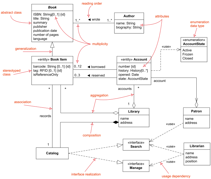
Class diagrams visually represent the classes that make up a system and the relationships between them. They are tools that show the system’s structure at a glance, like a blueprint for a building. To read and draw diagrams accurately, you need to understand their core elements first.
1. Class
A class represents a collection of objects that share the same attributes and behaviors. In diagrams, it’s shown as a rectangle containing attributes and operations.
- Class Name: Appears at the top of the rectangle. Conventionally, it’s bolded, center-aligned, and starts with a capital letter.
- Attributes: Represent the static data or fields a class has. They’re in the middle section and are left-aligned. Typically include the access modifier, name, and data type:
+: public-: private#: protected~: default (package-private)
Example:
userId,totalPrice
- Operations or Methods: The actions a class can perform. These go in the bottom section, also left-aligned, just like attributes.
Example:
login(),calculateTotal(),cancelOrder()
- Static Members: Static attributes or operations are underlined.
The UML standard recommends consistent ordering and line breaks for attributes and methods. For documentation within development teams, defining a separate “UML naming rule” for the team is a good idea.
2. Relationships
The real power of class diagrams lies in showing the relationships between classes clearly. Relationships are expressed primarily with arrows, and different arrow shapes indicate different meanings. The direction of the arrow indicates how one class uses another.
| Relationship Type | Meaning | Arrow/Symbol | Description |
|---|---|---|---|
| Generalization | Inheritance |  |
Indicates a parent-child class relationship. |
| Realization | Interface implementation |  |
Used when a class implements an interface; shown with a dashed arrow. |
| Association | Reference relationship |  |
One class holds another class as an attribute. The direction shows the reference flow. |
| Dependency | Temporary usage |  |
One class uses another as a method parameter or return value. |
| Aggregation | Weak whole-part relationship |  |
A “whole” contains “parts”, but the part’s lifecycle doesn’t depend on the whole. |
| Composition | Strong whole-part relationship |  |
The part’s lifecycle is entirely dependent on the whole. |
Example
Let’s say you’re developing an e-commerce system. You could express the interaction between the ‘User’, ‘Product’, and ‘Order’ classes with a class diagram:
classDiagram class User { - userId: int - name: string - email: string + login(): void + logout(): void } class Product { - productId: int - name: string - price: float + getInfo(): string } class Order { - orderId: int - date: Date - total: float + calculateTotal(): float } User "1" --> "1..*" Order : places > Order "1..*" --> "1..*" Product : contains >
Class diagrams act as a blueprint for the system and are highly effective in sharing structure among team members in the early stages of development.
Advanced Concepts: Abstract Classes and Interfaces
In object-oriented design, abstraction is a key concept. Class diagrams also offer ways to represent it.
- Abstract Class: A class that cannot be instantiated directly. Represented in italic text, or marked with
{abstract}or«abstract»below the name. - Interface: A set of operations that a class must implement. Clearly distinguished by placing
«interface»above the class name.
"Realization" and "Implementation" refer to the same concept. The official UML term is Realization.
When to Use Class Diagrams?
Class diagrams serve various purposes depending on the development phase.
- Conceptual Phase: Simply represents core classes and relationships of the system. Focused on understanding business logic.
- Specification Phase: Before coding, defines all attributes, methods, and relationships in detail. Acts as a blueprint for developers.
- Implementation Phase: Reflects the actual code structure and is useful for maintenance or explaining the code to others.
First Step Toward Better Development
We’ve now explored everything from basic concepts to advanced uses of UML class diagrams. Drawing a class diagram isn’t just about sketching—it’s a process of deeply thinking about system architecture and clarifying complex relationships. It may feel awkward at first, but with consistent practice, you’ll develop the habit of designing structure before writing code. Try applying class diagrams to your current or side projects. This small step can significantly improve your development productivity and design skills.
《UML Distilled》 is a classic written by Martin Fowler and the most efficient introduction to UML from a practical perspective.